山岳を活用した見通し外通信
Beyond-line-of-sight communication using mountains
by Tsuneyuki Kondoh, JA5GYU
1. Introduction
Recently, microwavers’ activities have been increasing in Japan.
They establish clubs, perform roll calls, domestic expeditions, and open workshops.
Of course, some of them make more QSOs from portable sites.
For a long time they believed that it was quite difficult to perform communications beyond
line-of-sight; however, it has become possible by using troposphere and rain scatter.
Nevertheless, these atmospheric propagations do not always provide us chances.
In contrast, communications via mountains are always possible over the line-of-sight.
I have made QSOs via mountain refraction and reflection on the VHF and UHF bands
and succeeded in microwave QSOs. This is a report of my three-year experiments of
mountain refraction and mountain reflection. I was serious about these propagations
because I live in a town surrounded by the sea and mountains. Note that my line-of-sight
is limited to only 150 km.
2. Mountain refraction and reflection
If a mountain lies between two radio stations and if it is visible from both stations,
radio wave from one of the stations is refracted at the mountain peak to reach another station.
Mountain refraction is often used on VHF and UHF bands although the refracted signal
is so weak that the number of demonstrations and experiments is small on the microwave bands.
If two radio stations are at the same face of a mountain, their signals reach each other after
mountain reflection. Reflection communications are popular on VHF-SHF bands.
3. Experiment arrangement
1) Equipment
We prefer larger dishes but a diameter of between 90 cm and 1.2 metres is practical.
A commercial 50-mW transverter was used with a 2-Watt linear amplifier.
The power of 2 Watts is a Japanese legal limitation. As a low-noise RX amplifier,
we used a GaAs amplifier with a NF of 2 dB and a gain of 20 dB. In order not to
vibrate the antennas, a heavy tripod was used.
2) Partner
I looked for a partner who keeps the similar interest, skill, and equipment.
3) Investigation and preliminary inspection
Map: We prepared a cross section map, referencing commercial maps.
QTH (refraction): We looked for QTHs, where the number of refraction is only one.
QTH (reflection): We looked for a mountain and QTHs unless the refraction is possible.
Preliminary inspection: We carried out preliminary inspection when it was possible.
4) Must items
Map, compass, altitude meter, beacon, radio, and cellular.
5) Time chart
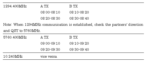
We arranged schedule details in advance. Time charts include start time, frequency, and TX/RX interval.

4. Experiments
The antennas should be erected, where they can see the partner’s direction.
They should not be hidden by other obstacles. For our negotiation and propagation estimate,
we used 1294MHz SSB radios. The usage of 1294MHz radios is strongly recommended.
Next, let’s start 5760MHz. Follow the prepared time chart. The station tha can
measure the partner’s direction more accurately transmits first.
Use SSB at the RX station. When an extremely weak signal is expected,
transmit modulated-CW and receive it in the SSB mode if you want to succeed
in SSB QSO finally. Transmitting and receiving SSB might be difficult at some circumstances.
The RX station concentrates on finding the frequency and finding the direction simultaneously.
If the RX station detects the signal, fix the antenna direction and let it know the TX station.
Then, switch TX/RX. When the turned RX station finds the better direction, they should
communicate each other in turn. They usually have fading and, then, direction finding needs
some experience. If the signal is strong enough, let’s try FM.
Finally, do the same thing on 10 GHz.
When you finish all the schedules, make documents. You should file the site photos,
logs, cross section map, and simulation results for further trial.
5. Results: QSO examples
Table 1 is a list of my QSO examples of mountain refraction and Fig. 1 shows some
of the paths. In most cases, we succeeded in the QSOs on all the bands between 1.2 and 10 GHz.
The 5.7GHz propagation is the best in the SHF bands. We feel shallow fading but
the propagation is stable.
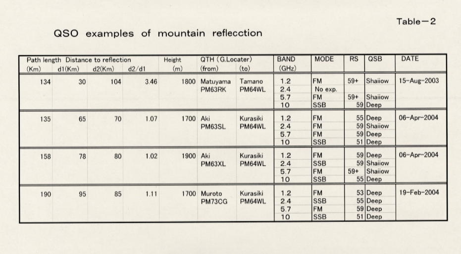
The results of mountain reflection are shown in Table 2 and Fig. 2. The QSOs were successful
as well as the mountain refraction. In contrast to the mountain refraction, the reflected
signals reached with deep fading and the tones were distorted due to multiple-path interference.
We sometimes heard the signals with echo. If the FM signal was strong enough, FM QSOs were
also successful, as indicated in Tables 1 and 2. When one of the stations are close to a
mountain (ratio |d2/d1| >1), the signal was large. This agrees to a textbook propagation theory.
Figures 3 and 4 show the cross section maps for >400 km DX QSOs. As can be seen in these figures,
two points are far away from the ‘line-of-sight’, although the radio signals travel to the
partner after once or twice the refraction.
6. Summary
Even amateurs surrounded with mountains can enjoy communications on microwave bands by fully
utilising the mountain refraction and reflection. We experimentally estimate the communication
limits to be 600 and 300 km via mountain refraction and reflection, respectively. If the
circumstances are sufficiently good, 5.7GHz signals can reach DX like VHF and UHF signals.
We noticed that the 10GHz QSO is also possible in most cases when the 1.2GHz QSO is successful.
QSO was possible even from the shore site in Tosa City, Kochi Prefecture. Figure 5 shows my
portable station. The antennas used are a 90-cm dish for 5.7 and 10 GHz, a 32-el Yagi for 1.2 GHz,
and a 36-el Yagi for 2.4 GHz. Why don’t you try this?
Figure captions
Fig. 1 Paths via mountain refraction.

Fig. 2 Paths via mountain reflection.

Fig. 3 An example of cross section map of the mountain refraction QSO.

Fig. 4 Another example of cross section map of the mountain refraction QSO.

Fig. 5 Tsuneyuki’s portable shak.

Table 1 QSO examples of mountain refraction.

Table 2 QSO examples of mountain reflection.

戻る
Mail to Webmaster


